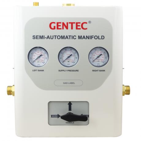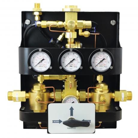

GM1 series dome-bias semi- automatic manifold system is designed to provide an uninterrupted gas supply. It consists of a primary bank and a reserve bank of cylinders. When the pressure in the primary cylinder bank reduces the preset value, the changeover takes place automatically to provide continuous supply of gas from the reserve bank. The priority handle should be manually switched during cylinder change.
Features
Semi-automatic Changeover System
• Fully enclosed, dust-proof metal cabinet
• Pressure gauge indicates gas source and outlet pressure
• Secondary regulator for consisent pressure and flow delivery to the pipeline
• Relief valve at outlet for protecting downstreampiping
• Pressure switch port is available
• Mechanical dome-dias changeover design
• Prior indicator valve
• Suitable for high flow systems; rated for 120m3/h (4200SCFH)* to 170m3/h (6000 SCFH)**
* When delivery pressure is 50 psi
** When delivery pressure is 180 psi
Pipeline
• Silver brazing on piping joints for maximum leak prevention
• System is designed to accommodate future expanison needs
• Optional external filter provides easy replacement of filter element
• Optional master shutoff valves
• Headers have been tested to withstand high cylinder pressure
• Wall or floor mount available
| GM1-A | L | - O2 | - U | - ( 5L - 5R | - S | 2 ) |
| Series | Delivery Pressure | Gas Service | Standard Code | Number of Cylinders | Manifold System Layout | Cylinder Valve Spacing |
| GM1-A | USA Standard L: 55 psi (380 MPa) M: 100 psi (690 MPa) H: 185 psi (1270 MPa)
EN Standard L: 72.5 psi (5 bar) M: 116 psi (8 bar) H: 145 psi (10 bar) | O2: Oxygen AIR: Air CO2: Carbon Dioxide IN: Argon, Helium, Nitrogen | E: ISO 32 U: NFPA 99 (USA) | 1L-2R: One cylinder on the left, Two cylinders on the right 5L-5R: Five cylinders on the left, Five cylinders on the Right 0-0: Left and Right side each with filter and master shutoff valve Note: Direction of piping (Right or Left) is indicated by facing the manifold. | S: Standard layout L: "L" Shape layout U: "U" shape layout D: Crossover layout X: Staggered layout | 1: 5" (127 mm) 2: 10" (254 mm) 3: 13" (330 mm) 4: 18" (457 mm) |
| Series | Gas Service | Max. Inlet Pressure psi (bar) | Delivery Pressure psi (bar) | Max. Delivery Flow SCFH (m3/h) | Outlet Connection | Pigtail Specifications |
| GM1-AL-O2 | Oxygen | 3000 (207) | 10~145 (0.69~10) | 4200 (120) | 3/4" NPT (M) | Pigtail, CGA540 |
| GM1-AM-IN | Inert Gas | 3000 (207) | 10~230 (0.69~15.86) | 6000 (170) | 3/4" NPT (M) | Pigtail, CGA580 |
| GM1-AM-CO2 | Carbon Dioxide | 2175 (150) | 4.4~125 (0.3~8.62) | 1060 (30) | 3/4" NPT (M) | Pigtail, CGA320 |
| GM1-AH-AIR | Air | 3000 (207) | 10~203 (0.69~14) | 5300 (150) | 3/4" NPT (M) | Pigtail, CGA346 |
* Connections can be changed to meet DIN, BS or other standards
• 24" or 36" flexible high pressure stainless steel braided pigtails with check valve
• Rigid copper pigtails are standard when gas service is oxygen
• Carbon Dioxide manifold systems are provided with H900G electric gas heater
• Siphon-type cylinder should not be used in the manifold system
| Gas Service | W in.(mm) | H1 in.(mm) | H2 in.(mm) |
| Oxygen, Air, Argon, Nitrogen, Helium | 41.3 (1050) | 15.8 (400) | 55.1 (1400) |
| Carbon Dioxide | 56.3 (1430) | 15.8 (400) | 55.1 (1400) |


| Standard Layout | "L" Shape Layout | "U"Shape Layout | Crossover Layout | Staggered Layout |
 |  |  |  |  |
Spec Sheet Files
| Attachment | Size |
|---|---|
| 4.42 MB |


