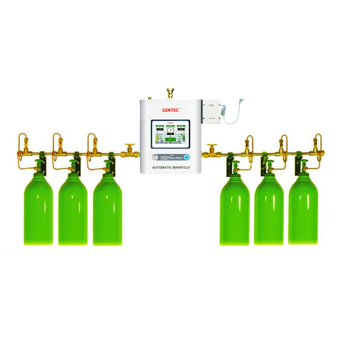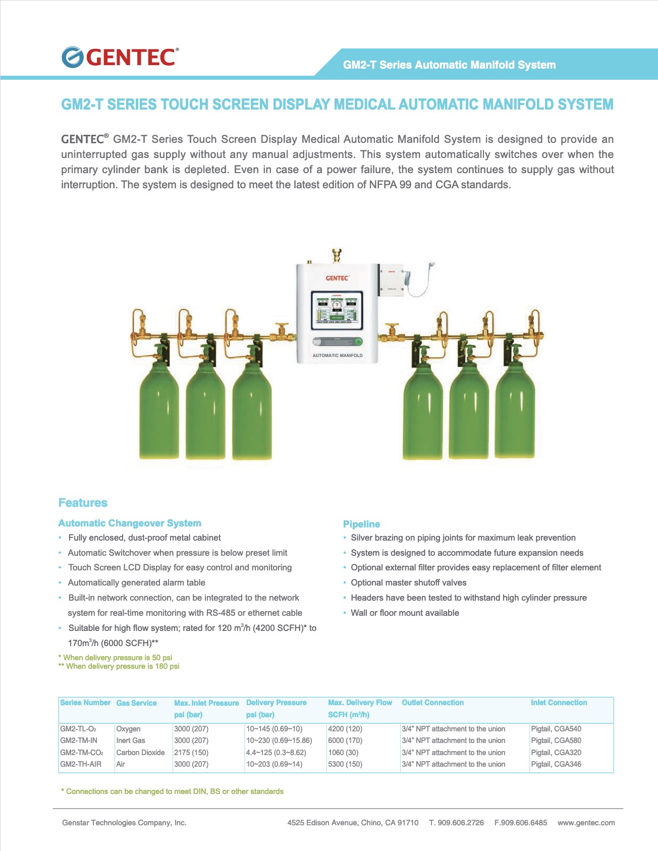


Touch Screen Display Automatic Manifold System
GM2-T Series Touch Screen Display Medical Automatic Manifold System is designed to provide an uninterrupted gas supply without any manual adjustments. The system automatically switches over when th eprimary cylinder bank is depleted. Even in the case of a power failure, the system continues to supply gas without interruption. The system is designed to meet the latest edition of NFPA 99 and CGA standards.
Features
Automatic Changeover System
• Fully enclosed, dust-proof metal cabinet
• Automatic Switchover when pressure is below preset limit
• Touch Screen LCD Display for easy control and monitoring
• Automatically generated alarm table
• Built-in network connection, can be intergrated to the network system for real-time monitoring with RS-485 or ethernet cable
• Suitable for high flow systems; rated for 120m3/h (4200SCFH)* to 170m3/h (6000 SCFH)**
* When delivery pressure is 50 psi
** When delivery pressure is 180 psi
Pipeline
• Silver brazing on piping joints for maximum leak prevention
• System is designed to accommodate future expanison needs
• Optional external filter provides easy replacement of filter element
• Optional master shutoff valves
• Headers have been tested to withstand high cylinder pressure
• Wall or floor mount available
Inquire about this product
Contact Us
Hours
Phone
Fax
Address
Chino, CA 91710, USA
Ordering Info
| GM2-T | L | - O2 | - U | - ( 5L - 5R | - S | 2 ) |
| Series | Delivery Pressure | Gas Service | Standard Code | Number of Cylinders | Manifold System Layout | Cylinder Valve Spacing |
| GM2-T | USA Standard L: 55 psi (380 MPa) M: 100 psi (690 MPa) H: 185 psi (1270 MPa)
EN Standard L: 72.5 psi (5 bar) M: 116 psi (8 bar) H: 145 psi (10 bar) | O2: Oxygen AIR: Air CO2: Carbon Dioxide IN: Argon, Helium, Nitrogen | E: ISO 32 U: NFPA 99 (USA) | 1L-2R: One cylinder on the left, Two cylinders on the right 5L-5R: Five cylinders on the left, Five cylinders on the Right 0-0: Left and Right side each with filter and master shutoff valve Note: Direction of piping (Right or Left) is indicated by facing the manifold. | S: Standard layout L: "L" Shape layout U: "U" shape layout D: Crossover layout X: Staggered layout | 1: 5" (127 mm) 2: 10" (254 mm) 3: 13" (330 mm) 4: 18" (457 mm) |
Specifications
| Series | Gas Service | Max. Inlet Pressure psi (bar) | Delivery Pressure psi (bar) | Max. Delivery Flow SCFH (m3/h) | Outlet Connection | Pigtail Specifications |
| GM2-TL-O2 | Oxygen | 3000 (207) | 10~145 (0.69~10) | 4200 (120) | 3/4" NPT attachment to the union | Pigtail, CGA540 |
| GM2-TM-IN | Inert Gas | 3000 (207) | 10~230 (0.69~15.86) | 6000 (170) | 3/4" NPT attachment to the union | Pigtail, CGA580 |
| GM2-TM-CO2 | Carbon Dioxide | 2175 (150) | 4.4~125 (0.3~8.62) | 1060 (30) | 3/4" NPT attachment to the union | Pigtail, CGA320 |
| GM2-TH-AIR | Air | 3000 (207) | 10~203 (0.69~14) | 5300 (150) | 3/4" NPT attachment to the union | Pigtail, CGA346 |
* Connections can be changed to meet DIN, BS or other standards
• 24" or 36" flexible high pressure stainless steel braided pigtails with check valve
• Rigid copper pigtails are standard when gas service is oxygen
• Carbon Dioxide manifold systems are provided with H900G electric gas heater
• Siphon-type cylinder should not be used in the manifold system
Restrictions
![]() WARNING: Cancer and Reproductive Harm For more information go to www.P65Warnings.ca.gov
WARNING: Cancer and Reproductive Harm For more information go to www.P65Warnings.ca.gov


